WA1ZYX / KA1QFA/KB1QPC WQKQ332 |
![]()
My disclaimer for all of this is that I take credit for NONE of this, I'm only writing this page to assemble everything I've learned about this in one place, as it took a while to find everything I needed to know. I can however confirm that what I "did" learn, works. So, having said that, let's get going....
The first thing that needs to be done is to Hex Edit one of the .dll's buried in the computer for the software. I'm using CPS 06.12.02,
and the majority of the information I found pertains to that version. Also, I'm using HxD for a hex editor and that also works
flawlessly. The HxD software can be downloaded here.
The following instructions are exactly what I located off another site. I'll include some screenshots too as well as a few
useful hints.
Follow these exactly, and you'll find that you won't have any trouble programming the CDM's Out-Of-Band.
Now, I can not confirm on any other models or versions, nor can I confirm how far out of band you can go. I only know
that I accomplished what I needed to do, and here's how I did it. One more thing, BEFORE you hex edit anything,
back it up in case you screw up!
In your computer, navigate to Program Files, Common Files, Motorola, RDK and find "rui41.dll".
Once you find the .dll, go to properties, and uncheck the "read only" attribute, and save that. Now you can actually "edit" it.
Make this change with the hex editor:
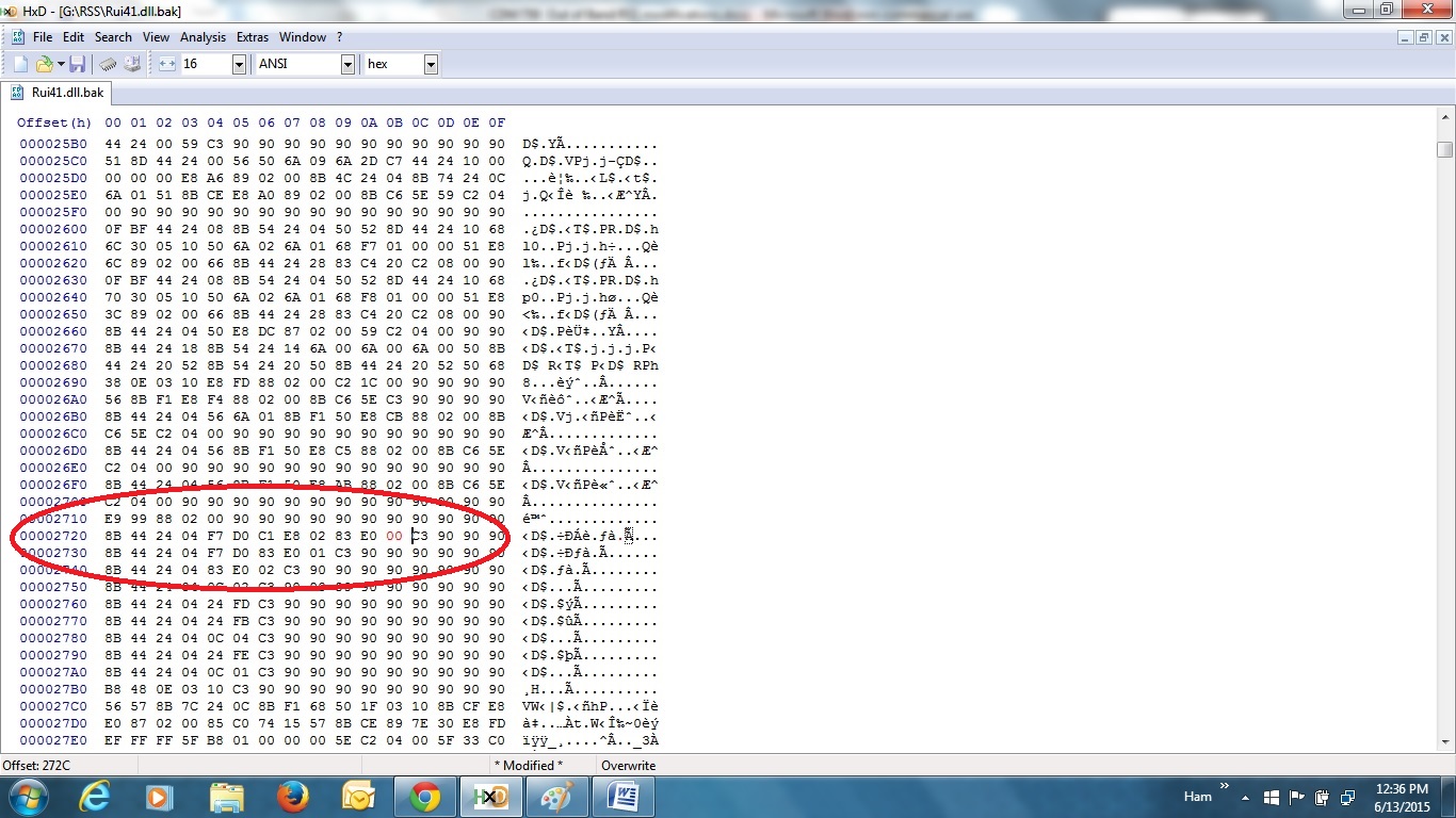
offset 0x00002720 "83 E0 01" change to "83 E0 00" - this file has been the same revision for all CPS versions for many years.
This change causes the normally 'read only' text boxes in the 'radio information' screens to become writeable.
After you've made the change, save it, go back to properties and re-check the "read only" attribute.
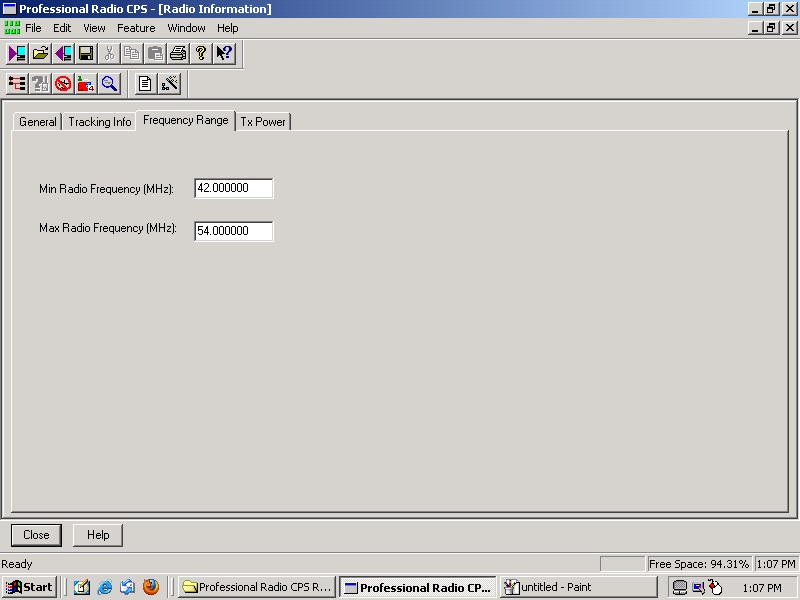
Step two is to stop the CPS from throwing up errors when you try to write an out of band codeplug to the radio:
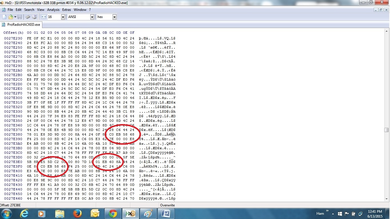
In proradio.exe modify and save the following:
offset 0027E380 - change "75 58" to "EB 58"
offset 0027E3E0 - change "75 60" to "EB 60"
offset 0027E3F0 - change "75 58" to "EB 58"
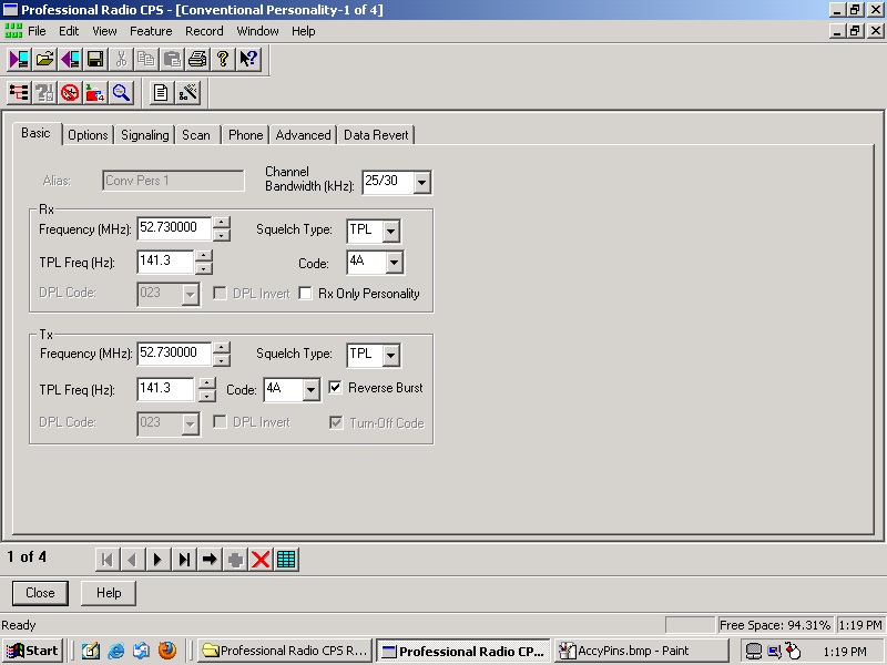
This next section will correct any issues that might happen if you should try to read or write to the radio and get
blessed with a "region mismatch" error. This involves actually editing your computer registry, and I can't stress enough
the importance of backing this up BEFORE attempting any editing of it. And no, I didn't learn the hard way, but
there are plenty of others that have....
On a Win7 computer, click Start, in the search field, type: regedit
Navigate to the following key:
HKEY_LOCAL_MACHINE\SOFTWARE\Motorola\ProRadio\FSK\SerializedString
Set the value to: "MAHUS" (without the quotes) and restart your CPS.
That pretty much covers it. I'll also include a few other tips and images for reference.
First, I did find out the hard way, that if you're going to use these radios in repeater service, you absolutely must
have the radio remember to "power up" should you have a power failure on the mountain top. So, make
sure you set the CPS Accessory Configuration, ignition sense type, to "On/Off & Ignition". You'll also obviously need to supply pin 10 of the Acc'y connector
with non-switched +12v from your power supply. This I did learn the hard way, as I programmed the radio w/o doing this and
once it re-booted, it wouldn't power up, at all! So that got me scrambling to jump that pin hot so I could get it to turn back
on to re-program it. Not a huge issued in the end, but initially I thought I'd bricked the radio. Whew....
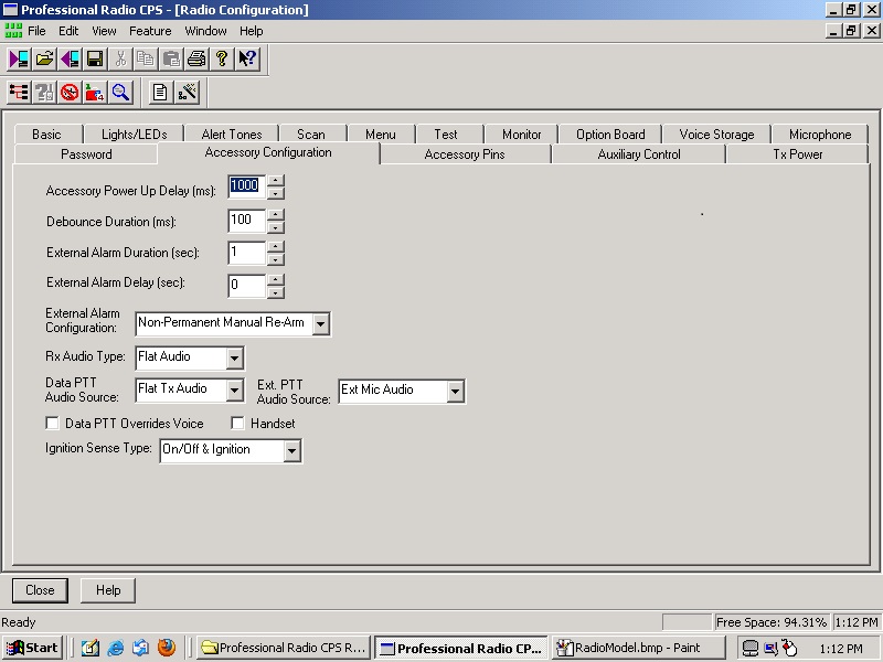
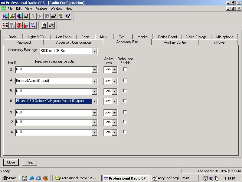
I also am just using this radio basically as a cross-band repeater, Lo-Band receiver to UHF transmitter, as the 6m repeater
is a split site. So, I decided to try one of those little repeater maker thingys, which does exactly what it needs to do, grab the
receiver audio and COR and stuff it into the link transmitter radio which is a UHF GM-300. One word of caution when using those
little gizmos, is to make sure you've got it orientated correctly and the radio acc'y pins are programmed correctly. I also added
the ignition sense line from pin 10 to the RX gizmo.
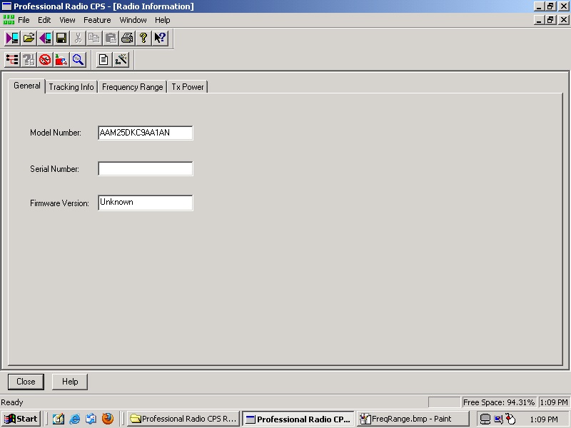
Model of CDM750 used for the project.
This is the end result, and showing the CDM receiving a signal and making the GM300 re-transmit it.
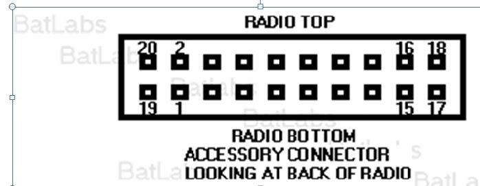
CDM 750 Accy Jack Pin-out
Mobile Radio Accessory Connector Predetermined Functionality
Pin Description Direction Comments
1 Speaker (-), Not Programmable
2 External Mic Audio, Partially Programmable
3 Digital In #1, Input Only, Fully Programmable, 12 Active Low Only
4 Digital In #2, Output Only, Fully Programmable
5 Flat TX Audio Input, Partially Programmable
6 Digital In/Out #3, Input Only, Fully Programmable
7 Ground, Not Programmable
8 Digital In/Out #4, Selectable I/O, Fully Programmable
9 Analog In #5, Special Input, Fully Programmable, Tri-state Emergency Switch
10 Ignition Sense, Special Input, Not Programmable, Active High
11 Flat RX Audio, Partially Programmable
12 Digital In/Out #7, Selectable I/O, Fully Programmable
13 Switched Battery (+), Not Programmable
14 Digital In/Out #8, Selectable I/O, Fully Programmable
15 RSSI (Radio Signal Strength Input), Not Programmable
16 Speaker (+), Not Programmable
17 BUS (+)*, Not Programmable
18 Boot Control*, Not Programmable
19 Unknown, Not Programmable
20 Unknown, Not Programmable
|
WebMaster WA1ZYX
|
If these pages don't look right, you're not using:
Download it now! |
Saddleback Mountain
| Saddleback Repeater Site | Cannon Mountain |
Cannon
Repeater Site | Temple Mountain | SWNH Node
System
Mt
Kearsarge |Winter Wonderland
| Surry Police | CCDX
Home | ZedYX Index | NH
Police 10-Codes
DISCLAIMER:
Modifications made to any equipment based on the information contained on this or
any ZedYX pages are AT YOUR OWN RISK!
![]()