|
WA1ZYX / KA1QFA/KB1QPC WQKQ332 |
|
WA1ZYX / KA1QFA/KB1QPC WQKQ332 |
![]()
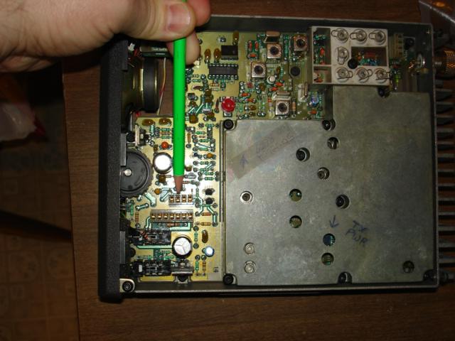
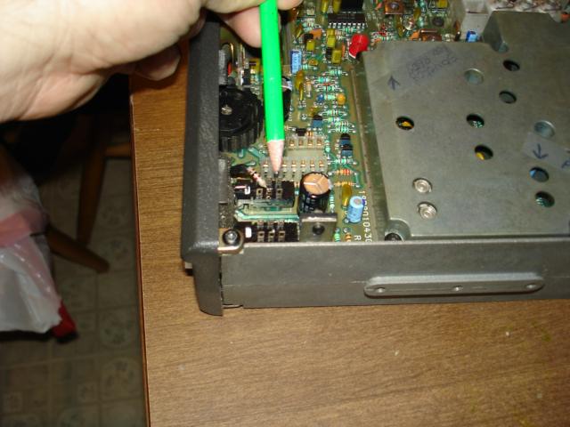
Now on the top side of the radio, locate the corresponding pin of J912, this
solder connection is actually the end of the pin that protrudes through the radio to
make contact with P912.
Solder wick this connection and while using needle nose pliers, heat the pin, and
pull it back through to the top side so there is a minimum of ľ of an inch of the pin
showing. This will ensure that you have broken the contact with P912. (It probably
isn't a bad idea to power up the radio at this point and confirm that the MODE A/B
switch DOES NOT work now.)
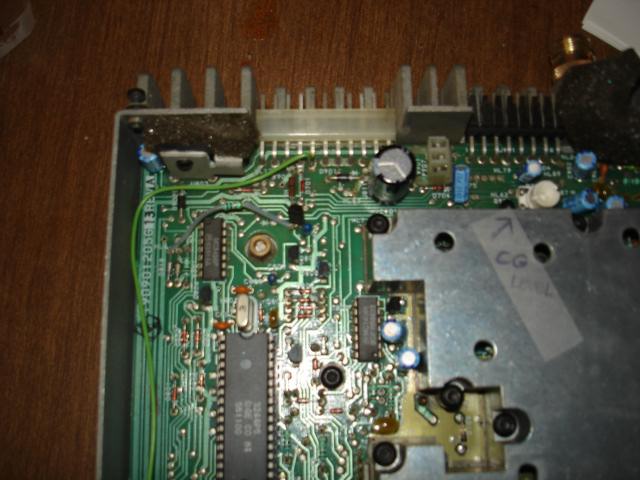
Position the radio with the front panel facing you, flop it over and locate
the A/B Mode switch (S601) on the underside of the radio.
Using a 1K 1/4w resistor, solder one end to the center tab of the A/B switch
(S601), on the row of tabs closest to the Monitor pushbutton. (The other row isn't
used, so if you make a mistake, it just won't work, you won't hurt anything.)
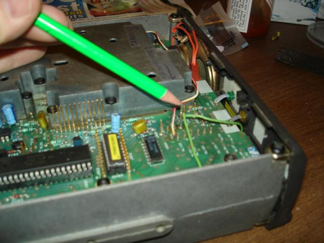
Solder one end of a short jumper to the other end of the 1k resistor and route
it to the top side of the radio so you can solder the remaining end of the jumper to
the Pin at J912. (The one you pulled through).
If you power up the radio now, the Mode A/B switch should be working normally
again. What the above mod does is make it possible to leave the A/B switch in
the "B" position (which actually supplies 8v to the microprocessor) and pull the
microprocessor line to ground (at J912) without shorting the 8v supply - thereby
gaining access to the "A" mode. The A/B switch is really nothing more than an on/off
switch for 8v to one of the microprocessors logic lines.
What I did next will allow, with the addition of a few pins in the power and
mic connector plugs, access via the rear panel to remotely change channels.
If you need pins or connectors, you can get them from
DigiKey.
The 11 circuit terminal housing, .156 for J910 is Digi-Key P/N WM-2109-ND
The 8 circuit terminal housing, .156 for J911 is Digi-Key P/N WM-2106-ND
And the Pins for housings are Digi-Key P/N WM2300-ND
Or you can get them from Mouser Electronics.
The 11 circuit terminal housing, .156 for J910 is Mouser P/N 538-09-50-3111
The 8 circuit terminal housing, .156 for J911 is Mouser P/N 538-09-50-3081
And the Pins for housings are Mouser P/N 538-08-50-0106
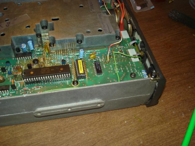
Now use another jumper and connect one end again to J912 and back to pin 5
of J910 (the 11 pin systems jack on rear panel.) Pin 5 is an extra pin and there
are no traces or other connections to it.
IMPORTANT, The rear panel jacks are labeled looking from the front of the
radio down at them. The 11-pin jack (J910) should be on the left, the Mic
connector (J911) to the right of that and the antenna jack on the extreme right.
Also the pin numbers are from Left to Right.
Now by pulling Pin-5 of J910 Lo, you can remotely toggle the electrical
position of the Mode A/B switch.
TO ACCESS THE REMAINING CHANNELS:
To change the frequencies, all you have to do is momentarily pull Pin-7 of
J911 to ground. By pulsing Pin-7 of J911 (Mic connector) to ground gives you access
to 8 channels, and by changing the condition of the A/B line gives you the other
bank of 8 for 16 total.
In order for this to work remotely, you need to leave the radio A/B switch
in the "B" position, and now externally pull pin 5 of J910 LO to put the radio
in Mode A.
Pin-Outs
As looking at pins from front of radio w/11 pin connector on LEFT
| J910 - 11 PIN SYSTEMS CONNECTOR | J911 - 8 PIN MIC CONNECTOR |
| Pin 1 +12VDC | Pin 1 Ground |
| Pin 2 HIGH GOING TOS | Pin 2 PTT |
| Pin 3 Ext Spkr HI | Pin 4 Mic HI |
| Pin 4 Filtered Vol/Squ HI | Pin 7 Ch Select |
| Pin 5 A/B Select Pull LO for A (After Mod) | |
| Pins 6,7 & 8 Ground | |
| Pin 9 CG Disable | |
| Pin 11 +12VDC |
DISCLAIMER:
Modifications made to any equipment based on the information contained on this or
any ZedYX pages are AT YOUR OWN RISK!
![]()
|
WebMaster WA1ZYX
|
If these pages don't look right, you're not using:
Download it now! |
|
Saddleback Mountain
| Saddleback Repeater Site | Cannon Mountain |
Cannon
Repeater Site | Temple Mountain | SWNH Node
System
Mt
Kearsarge |Winter Wonderland
| Surry Police | CCDX
Home | ZedYX Index | NH
Police 10-Codes
![]() Monday, September 10, 2007 10:05 AM
Monday, September 10, 2007 10:05 AM