|
WA1ZYX / KA1QFA/KB1QPC WQKQ332 |
|
WA1ZYX / KA1QFA/KB1QPC WQKQ332 |
![]()
I searched all over the net looking for info on these radios, and never really found an all-in-one place that had everything that I needed. One resource that was very helpful was the EFJohnson Yahoo group. There you can find some diagrams, the actual RSS and other hints and tips as well as the actual radio manuals, which were just recently posted in Feb of 07, but there still weren't any pictures to speak of, which I find very helpful. So..... As I am sure there are a gazillion of these radios out there, I'm going to attempt to document some of my findings here.
These mods are going to be based on the 7184 UHF 8-Channel radios, and as I found when going through the stack of radios that were given to me, there was a 7186 in the mix, so there will be some stuff on those as well.
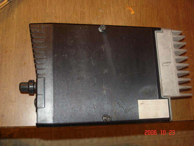
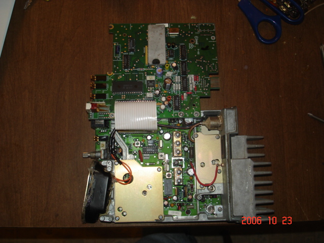
Bottom view of a UHF 7184. Remove the two screws on the bottom cover, the two concentric knobs on the front panel (Vol/Squ) and slide the case forward to remove it.
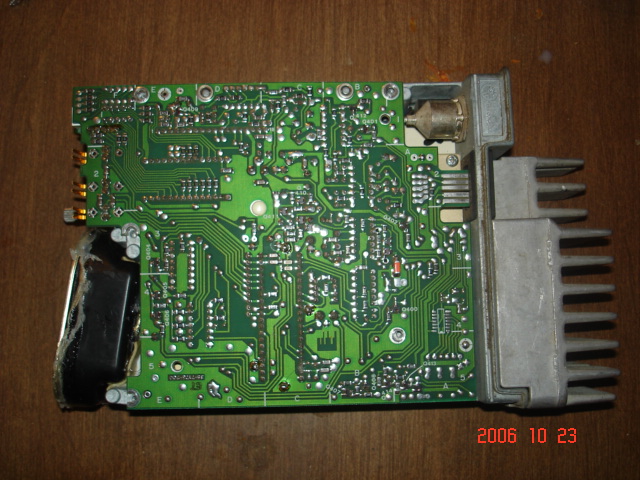
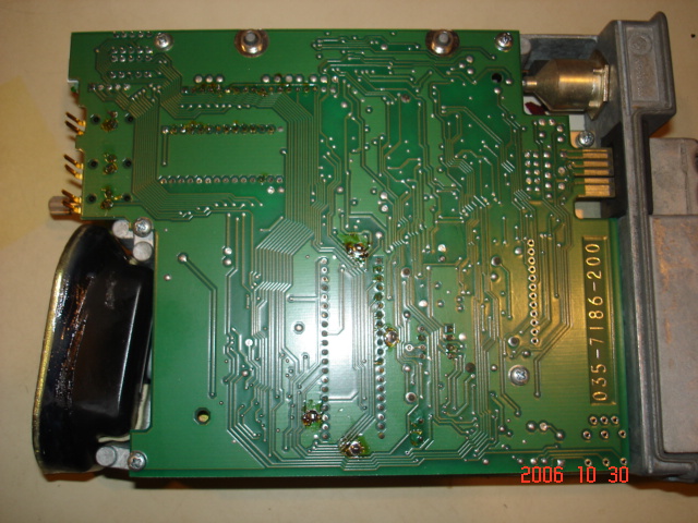
Solder side of the Audio/Logic board. The radio is actually sitting right-side-up in this photo.
While I was taking all the radios apart to clean them up, I got to about the 4th one, slid the case off, and said to myself, Hey, this one's a little different. New version? Nope, different model. This one's a 99 channel!!
Okay, back to the 7184.... Front of radio. Channel indicator on the upper left, stack of 4 LED's beside that.
Top GREEN = Busy, RED = Transmit, YELLOW = Message (when the correct CTCSS tone has been received, this LED comes on until the mic is taken off hook and returned, and the bottom GREEN = Monitor/Carrier Squelch.
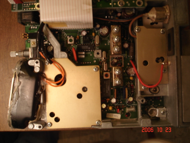
Radio separated. Remove 5 screws from the audio/logic board, flop it over and rest it on the two pegs along the edge of the chassis. Put a couple screws back in to hold that in place, and the radio will be very easy to work on. (The pegs and where to put the screws will become obvious once you open the radio up.)
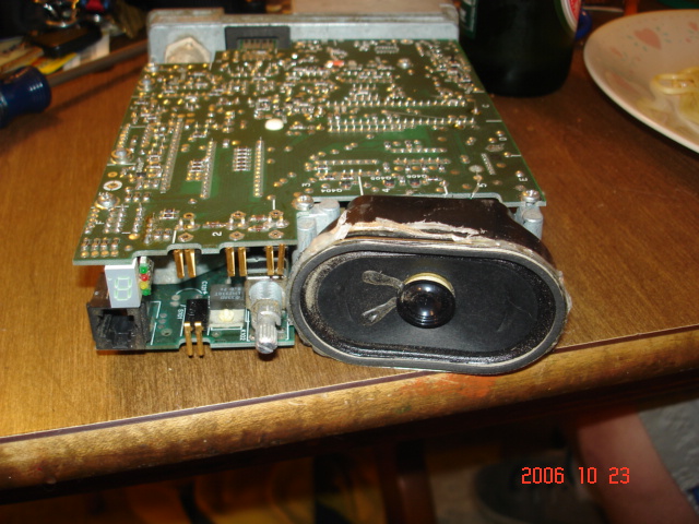
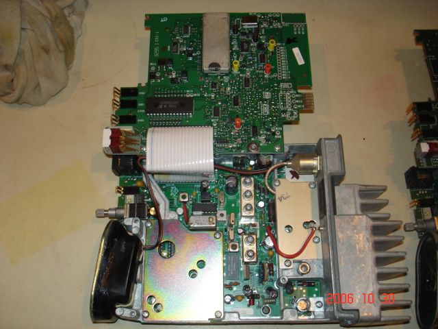
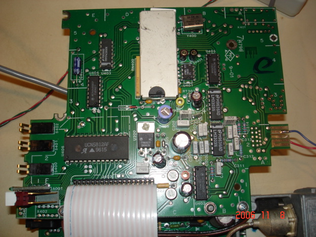
Upper half is the Audio/Logic board, bottom half is the RF board. Receiver front-end tuning are the 5 helicals just to the right of the synthesizer (directly behind the speaker)
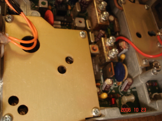
Closer view of the front-end tuning, and synthesizer shield.
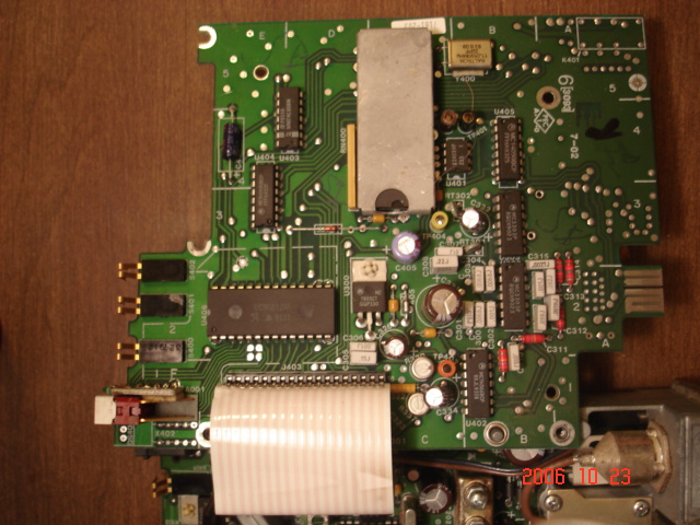
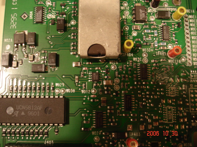
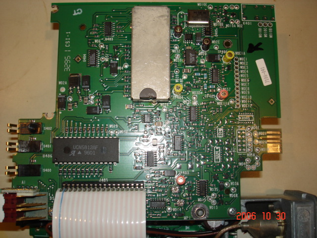
Audio/Logic component side. Most connections for repeater and link use can be found on the ribbon cable, however, COR needs to come from the busy light and TOR comes from Pin 13 of U402, located to the right of the ribbon cable.
The TTL programming connections for the edge connector are: (Also, see below for further info on programming)
As you look at the picture of the component side of the Audio/Logic board above, with the edge connector on the right, the pin next to the notch in the PC board is PIN 1, working toward the antenna connector, are pins 3, 5, 7 & 9. Notice Pins 7&9 are physically jumped together at ground potential.
Pin 3 = RX Data
On the solder side of the board, are the even pins. The pin closest to the notch in the PC board is PIN 2, then working toward the antenna connector are pins 4, 6, 8 & 10.
Pin 8 = TX Data
As I didn't have an edge card connector for my home made RIB, I just soldered my TTL lines directly to the radios while I was programming them. This turned out to work just fine.
J403 --- The Ribbon Cable -- Pin 1 is closest to the LED display
Pin ---- Description
1 - Filtered RX audio
2 - Channel Step Sw
3 - Mic Audio
4 - PTT
5 - Hanger
6 - Adaptive Filter
7 - Data
8 - Clock
9 - Enable
10 - Lock Detect
11 - TX Audio
12 - T/R select
13 - RX Detector Audio
14 - Squelch Noise
15 - 9V
16 - CPTT
17 - TOT Audio
18 - Ground
COR can be found on the solder pad closest to the front edge of the radio under the 4 LED stack on the audio/logic board.
And I've discovered by poking around, that TOR (CTCSS logic) can be located on Pin 13 of U402. Ground the Mic hang-up button, or better yet, ground Pin 5 of J403 and your receiver will be full-time tone squelch. Also you don't need the mic plugged in at all now.
I probably should mention that after I interfaced a repeater controller to the radio for COR and TOR, the controller loaded down the radio and things didn't work quite as planned. So, all that was required was the addition of a couple Mosfets to buffer the radio and now it plays just fine. Use a couple IFR510 Power Mosfets - Radio Shack P/N 276-2072 or equiv. Ground the Source lead, connect the Gate to the radio logic points and then, run the Drain to the controller. Easy, dirt cheap and works flawlessly!
I've also had a few inquiries about the pin-outs of the front panel Mic Jack, so...
J103 - Pin-outs:
| 1 | Ground |
| 2 | Mic Audio HI |
| 3 | Hang-up / Monitor |
| 4 | PTT |
| 5 | +13.8vdc (If internal jumper is installed |
| 6 | NC |
Close up of the synthesizer shield. See that BLUE pot standing on end by the helicals? That's R163, the TX Power output adjustment.
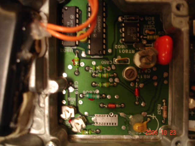
Cover removed from the synthesizer. That silver IC looking thing along the bottom edge is where you may need to either remove or add jumpers to adjust the VCO control voltage.
If you need to re-program your radio, you're going to need the RSS, and a TTL/RS232 converter to put between the radio and your DOS computer. No windows stuff allowed here. Run the RP7175.exe application.
I ended up building a Radio Interface Box out of parts obtained from Mouser Electronics from the schematic below. This diagram came from the Yahoo Group, and as you can see, it's pretty simple. About 3 bucks worth of stuff and a little solder and you're good to go.
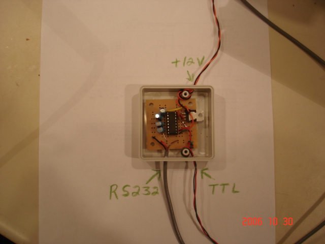
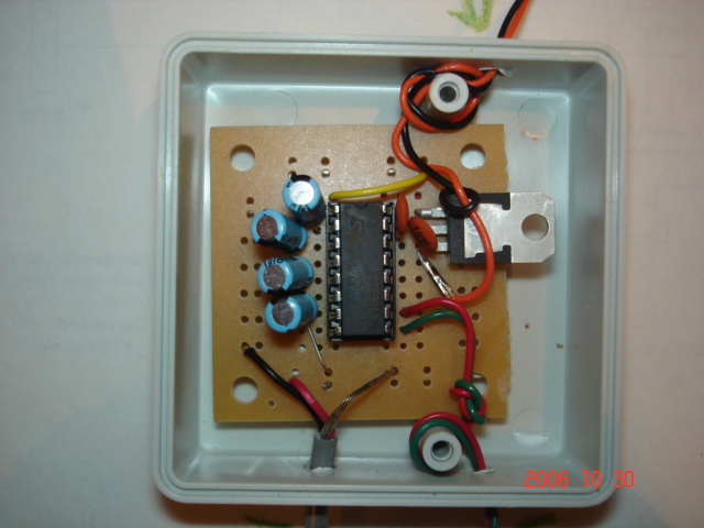
It aint pretty, but there it is... The homebrew RIB... And it works just fine!!!! Also, I found out that this RIB works on Kenwood TK-862G's. As you look at the front panel of the TK, Pin 1 of the mic jack is on the right and pin 8 is on the left. The data lines are Pins 4 & 7.
Make sure when you put on the DB9 for the computer connection, that you jump pins 4 & 6, and also jump pins 7 & 8 to take care of any hand-shaking issues.
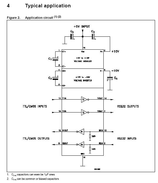
Schematic of the MAX232 Chip.
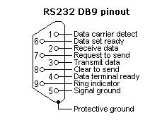
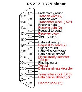
RS232 Pin Assignments
|
DESCRIPTION |
MOUSER PART # |
QUANTITY |
| 5V RS-232 Interface | 511-ST232EBN | 1 |
| 50V 1.0uF 20% Electrolytic Caps | 140-XRL50V1.0-RC | 4 |
| 50V,.01uF, Ceramic Disc Caps | 140-50U5-103M-RC | 2 |
| +5.0V 1.0A TO-220 Voltage Reg | 511-L7805CV | 1 |
| Plastic Project Box | 546-1593JGY | 1 |
| Dual General Purpose IC PC Board | Radio Shack 276-159 | 1 - Well, actually 1/2 of it..... |
To program the radio after you've built the level converter, if you need to, and you're running the RP7175.exe program on your DOS computer, you can do a couple different things. Either "READ" the radio to see what's in there, or "Create" a new file and just "WRITE" to the radio with your new file. I personally, would read the radio first and SAVE that file, then you'll have a known good file to work from.
After you've read the radio, you can edit that file to change the frequencies and then write that to the radio. You can also save this new edited file, naming it something else.
Some things I found out by trial and error... When you have everything all hooked up and turned on... The computer is connected to the RIB, the RIB is connected to the radio, both the radio and the RIB are powered up, when you get ready to either "READ" or "WRITE" to the radio, you'll be asked to turn the radio off, connect the RIB, which I already had connected and found didn't make any difference, then when you turn the radio back on, it's in "program" mode. READ it or WRITE to it, then turn the radio off for a few seconds and when you turn it back on, it should be all re-programmed.
If the channel display flashes and the radio beeps about twice a second, that's telling you that your synthesizer won't lock on the frequency you programmed in there and you're going to have to screw around with C856 & C857 in the synthesizer.
|
|
CTCSS / PL / CG Tone List
7186 laid open. Notice there are now two LED channel segments and all the service mount stuff, but otherwise, it's pretty much identical. Quickly looking, I only saw two immediate differences on the RF board. The squelch pot for the remote head is present, and there's an ICOM just above the synthesizer shield.
7186 Audio/Logic board.
7186 showing J403 and U402, now labeled as W011, to the right of the red TP403. Part number is the same, except it's for the SMD style device.
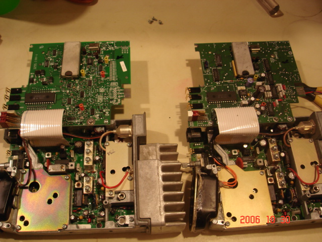
7186 on the left, 7184 on the right.
Programming info and RSS Screen Shots.
7184 Audio/Logic board showing programming connections. The blue wire is connected to Pin 3 for RX Data.
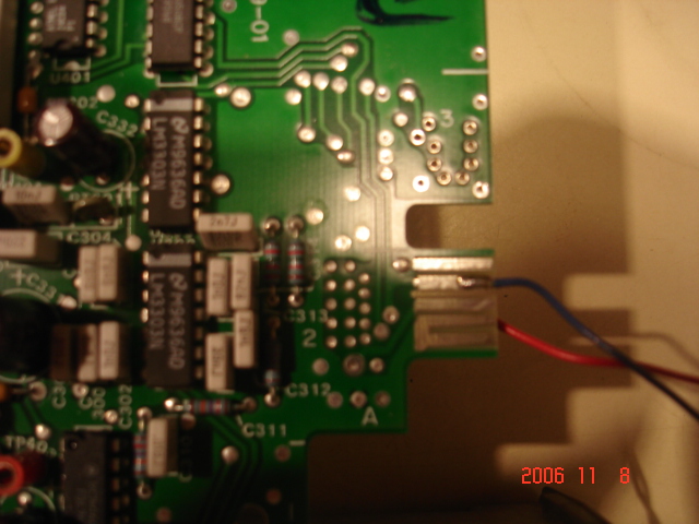
Close-up of Pin 3 connection
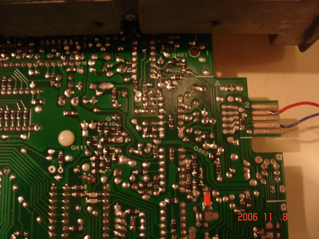
Here, the red wire is connected to Pin 8, TX Data.
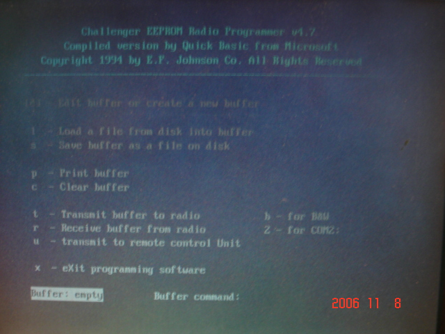
When you first start the RP7175.exe program this is the opening screen.
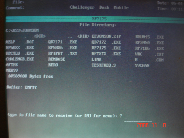
After selecting "r" to Read the radio, type in a name for the file.
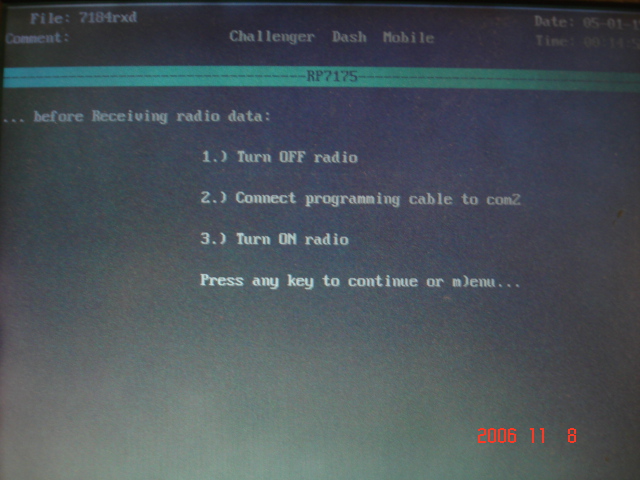
After you type in the file name, you'll need to turn off the radio, then turn it back on to put it into program mode.
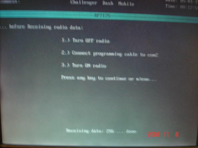
You can watch the progress of the radio being read. (Sorry for the blurry picture...)
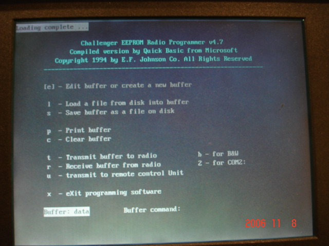
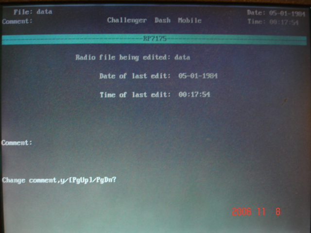
After you read the radio, you're brought back to the main screen. Notice upper left corner where it tells you that loading is complete. At this point, if you select "e" to edit what you've just read. If you select PgDn, you can then edit your frequencies. If you select PgUp, you go into radio-wide configurations, for example, Time out timers, scan priority channels, options for the two pushbuttons above the vol/squ controls etc...
Entering PgDn to edit frequencies
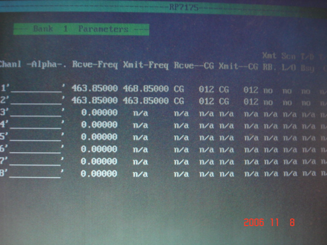
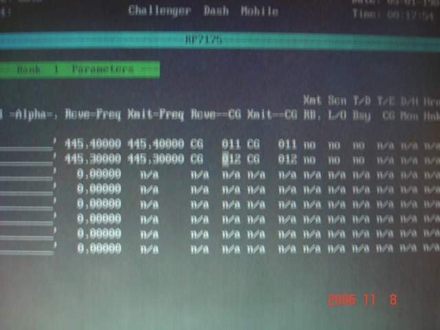
The frequency entry screen. Use your arrow keys to move between fields.
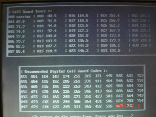
When your cursor is in the PL field, F6 will present the below screen so you can select which code to enter.
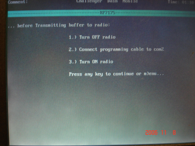
After you've made all your changes, press ESC to get back to the main screen and select "t" to send your data to the radio. Don't forget to turn the radio off then back on to put it into program mode again.
These radios were all originally programmed in the 460Mhz range. I wanted to use them on Amateur frequencies. All I had to do was enter the frequency. No needing to hold the shift key while going out of band or crazy stuff like that. However, the synthesizer wouldn't lock on anything below 450. Not to worry though, a couple tweaks on the caps in the VCO, C856 & C857 and they worked great. You're still going to need to realign the front end, but that's easy!!
|
WebMaster WA1ZYX
|
If these pages don't look right, you're not using:
Download it now! |
|
Saddleback Mountain
| Saddleback Repeater Site | Cannon Mountain |
Cannon
Repeater Site | Temple Mountain | SWNH Node
System
Mt
Kearsarge |Winter Wonderland
| Surry Police | CCDX
Home | ZedYX Index | NH
Police 10-Codes
DISCLAIMER:
Modifications made to any equipment based on the information contained on this or
any ZedYX pages are AT YOUR OWN RISK!
![]()
![]() Monday, September 10, 2007 10:05 AM
Monday, September 10, 2007 10:05 AM