Mods By:
Joel Huntley - WA1ZYX
Home Page
E-Mail
This page describes what needs to be done to modify a DB Products DB-212
folded dipole antenna only, not the cable harness if there is one.
These antennas were a favorite among the paging industry for their lo-band
operations, primarily in the 43 Mhz range. This mod will only cover the
conversion to the 50 Mhz band.
With all the changes over to higher frequencies, these antennas are now
finding their way into the surplus market and we hams love 'em for 6 meter
work. They're rugged, reliable, and more than likely FREE just for the asking.
As long as you know who to ask - but please, don't ask me!
 The antenna itself is constructed of 3 different diameters of aluminum tubing,
one sliding into the next, tuned to the paging company frequency and then
riveted and "dimpled" in place. The largest diameter tubing on the side furthest
from the mounting structure, that extends from the center mount is actually one
solid piece strictly for physical strength. It will be screwed (mounted) to the
center mount.
The antenna itself is constructed of 3 different diameters of aluminum tubing,
one sliding into the next, tuned to the paging company frequency and then
riveted and "dimpled" in place. The largest diameter tubing on the side furthest
from the mounting structure, that extends from the center mount is actually one
solid piece strictly for physical strength. It will be screwed (mounted) to the
center mount.
We will be working with the smallest diameter tubing that makes up the trombone
end of the antenna.
Drill out the rivets that are about 4 inches from where the smallest diameter and
the next section of tubing join. Also drill out the dimples very close to the
end of the tubing near the rivets. There will probably be 3 dimples at each
junction. Do this at all 4 junctions. (4 rivets and 12 dimples)
At this point, the trombone should slide. If it doesn't, you may need to
loosen the plastic spacer near the largest diameter and the middle diameter tubing. Also
a little penetrating or cutting oil might not hurt to break up the oxidation.
Once the trombone will slide, remove it - pull it right out. Now use a hacksaw
and cut a slit lengthwise in the tubing where you drilled out the dimples about
2 inches deep. I usually make the cut go through the holes left by where the
dimples were.
You will need some stainless steel hose clamps to re-secure the trombone after you
re-insert it into the slotted end of the tubing. Remember to slide the hose clamps
over
the tubing BEFORE you re-insert the trombone!
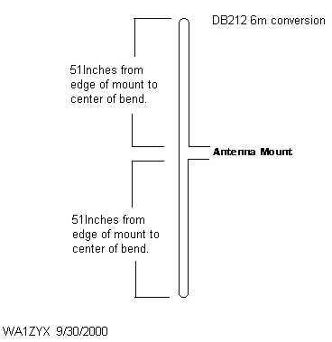
Now to determine the length. Using the standard formula: 468 / freq in Mhz, will give
you the length in feet. Multiply your result by 12 and you will now have a pretty
good beginning point in inches for the length of each element as measured from the
center (mount) to the end of the trombone.
You will need to make final adjustments using Mr. Bird - or some other type of
SWR measuring device or analyzer. However you will now be in the ball park.
Use the link below for a very handy page to do all the math for you. Just remember the
results will be in FEET and you need INCHES.
Frequency to length Conversion page
written by W4RLD.
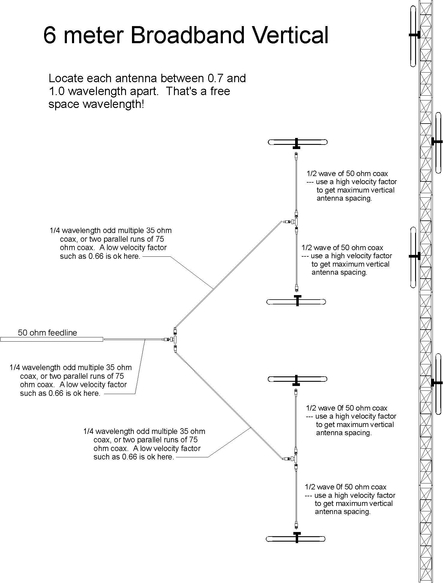
Thanks to Bill, N4LG for sending along the below image on the measurements
and cables needed to construct a new harness. According to Bill, after a
fairly lengthy conversation with a DB engineer and a few feet of RG-83, 35 Ohm
cable, he was able to build this harness.
The following is provided additional info from John - W1GPO
(Thanks John, de Joel..)
A few things we have learned about the DB 212 antennas:
The length of coax between the
antennas and the tee can be any length, just as long as they are equal.
The highest gain is about .95
wavelength center to center, but is close between 0.8 and 1.2 wavelength, with
not much further degradation way over 1.2 wavelength.(see ARRL Antenna
Handbook under collinear arrays for graph)
It is important not to be just
under a guy wire. Any metal that the antenna sees as vertical needs to be at
least 1/4 wavelength away, and will
affect the gain pattern.
The tower or mast must be
non-resonant and extend at least 1/4 wave above and below the antennas.
These antennas couple half of the
RF into the tower or mast, so any loose metal attached anywhere on the
tower, or feedlines often will cause duplex "scratchies".
If at all possible, use the
existing VB-8 coax as it is extremely durable to weather, UV, and water
penetration.Do not use coax with braided center conductor, or non-flooded
shield braid, or water will get in.
The VB-8 and VB-83 35 ohm coax are
made by Times Wire , Wallingford, Ct., for DB products.They may still be
available from Tessco, and possibly if you get the right person at Times Wire.
To get the optimum length of the
1/4 matching section of VB-83, attach a 50 ohm load to each end of the tee
that is to be used,(any length), fasten the 1/4 section the way it will
be, and add a random non-1/4 wave of 50 ohm coax between it and an antenna
bridge. It may take a few attempts to get the correct length for 1:1 SWR, at
the antenna freq., then attach the antennas.
DB Vapowrap or similar putty type
coax seal, covered by Scotch 88 tape is probably the best way to keep water
out of the tee, which is a difficult job.
Soldering the flooded braid is
difficult, but definitely possible if the copper is a shiny bright.Silver
plated PL-259 or silver plated PL-259 style N males work well.Clamp type N
connectors are mechanically weak. The VB-83 takes a 9913 sized center
pin.
Wrapping the elements with vinyl
tape, to reduce precip static, and the addition of a 1/8 inch water drain
hole at the very bottom of the lower element is probably a good idea.
Use conductive Noalox,or
Penetrox,etc, in the antenna tubing joints, especially if they are
exposed and hose clamped.
W1GPO