ccdxlogo.gif (6842 bytes)

WA1ZYX / KA1QFA/KB1QPC

WQKQ332


Modifications to a Motorola Micor Compa-Station Unified Chassis for Repeater Controller Interfacing.


Mods By:

Joel Huntley - WA1ZYX
Home Page
E-Mail

These Mods have been successfully used in interfacing S-Com 5K's and 7K's to Motorola Micor Compa-Stations with a Unified Chassis.

Items needed:
3) IFR510 Power Mosfets - Radio Shack P/N 276-2072 or equiv.
A couple strips of Double-Stick tape. Not necessary, but nice.
A short length of small shielded audio or rf cable.
About a foot of some kind of small insulated wire.


The first thing you need to do, is make sure you have a working unit prior to doing any modifications. This will make life much easier if you need to troubleshoot something later. Also, if you don't already have one, get a service manual!

Next if you have a unit that is configured as a Base Station, Tone or DC Controlled Remote Base, you'll need to modify the receiver interconnect board to allow DUPLEX operation. This is a very easy mod. Just get to the receiver interconnect board and remove diode CR 957.
** If it's configured as a repeater, then the above mod will have already been done. **

You can also get rid of ALL station cards/modules except the Station Control card.

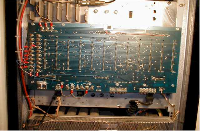
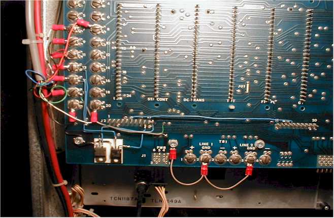
J2 on the backplane is the row of 30 pins in groups of 10 along the bottom of the backplane.
These are the Receiver interconnect pins.

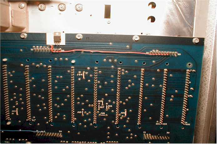
J5 on the backplane is the row of 30 pins in groups of 10 along the top of the backplane.
These are the Transmitter interconnect pins.

Install the following jumpers on the backplane using some insulated bell wire or whatever you have handy.
Jumpers:
J2-6 to J2-14 Enable Local Audio so no Line Driver card or Squelch Gate card are needed. (This takes preamp audio and sticks it into the audio amp for local audio.)

J2-26 (Gnd) to J2-30 (F1 RX) to Enable RX Osc (This turns on the receiver oscillator for position F1.)

At this point, with all cards removed except the Station Control card, your unit should receive and you should be able to hear audio from the local speaker.

There are six Philips head mounting screws along the bottom edge of the backplane. Looking at the lower left corner of the backplane, just to the right of the first mounting screw, you will see an area that is pretty clear of all traces. This makes a great spot to use some double-stick tape to mount two of the Mosfets.

Complete Backplane


Mount two of the Mosfets on the double-stick tape with their legs sticking up.

Prep two Mosfets:
Mosfet #1
With the Mosfets placed so that their legs are sticking up;
(The leads will be Source on Left, Drain in Center and Gate on the Right)
Bend the SOURCE lead of one Mosfet 90 degrees to the LEFT.
Clip the GATE lead, where it widens to enter the body.
Leave the DRAIN lead sticking up.


On the other;
Mosfet #2
Clip the SOURCE lead at the point it widens to enter the body.
Bend the GATE lead 90 degrees to the RIGHT.
Leave the DRAIN lead sticking up.


These will be mounted on the double-stick tape and arranged so that the CLIPPED Leads are closest, and BENT leads are on opposite ends.
That is, Mosfet #1 on the LEFT and Mosfet #2 on the RIGHT.

Jumper both Source leads to ground. (Use the backplane mounting screw just to the left of the Mosfets for your ground.)

Cor & Tor Mosfets


I also use the large screws staggered vertically along the left edge of the backplane to interface the controller. There are several screw terminals that don't have any signals on them and with a couple jumpers, you can get all the signals you'll need.
These are labeled TB3.

Install a jumper from TB3-19 to the mounting screw on lower left of backplane to establish a good ground.

RECEIVE AUDIO (Discriminator - un-squelched)

Locate J1, labeled as PWR next to the second mounting screw along the bottom edge of the backplane.
The traces you want to use are located by looking at the PWR jack. (J1)
There's a fairly wide trace that has the "R" from PWR with the "4" under it. This is a GROUND trace. You can meter it out with any other ground reference to make sure. Now, follow this trace up the backplane to where it ends at a feed thru rivet. It's a very short trace. It should be the Right feed thru in a set of three.

DIRECTLY ABOVE this feed thru rivet are 2 more feed thru rivets. They just look like Dots of solder. The one on the LEFT is the point to get Disc Audio. There is NO trace coming from this point.
(Just as a reference, the one on the right has a trace that you can follow to J2-11. That way, you'll know you've got the correct one.)

Prepare a length of small shielded audio cable, or RG174 RF cable so that the center conductor can be soldered to the feed thru that has Disc Audio on it, and the shield can be soldered to the ground feed thru right below it.
For the other end, solder the center to TB3-17 and the shield to TB3-19

COR TB3-13 - RX COR Input to Controller (Active Lo)
Install a line from J2-9 to the Gate of Mosfet #1.
Install a line from the Drain to TB3-13
You've already connected the Source lead to ground.


PL TB3-15 - RX CTCSS Input to Controller (Active Lo)
Install a line from J2-10 to Gate of Mosfet #2.
Install a line from the Drain to TB3-15
You've already connected the Source lead to ground.


Now to get the transmitter going.

Take another piece of double-stick tape and mount it above J5 over pins 19 and 20.

Take the third Mosfet and hold it facing you with it's leads pointing down and bend the GATE lead 90 degrees to the left. Leave the other two leads as they are.
Now mount the third Mosfet on the tape so that the right lead (Source) can be soldered to J5-20 (Ground) and the center Lead (Drain) can be soldered to J5-19 (F1 TX Osc).

Install a line from the Gate lead - should point towards the left - to J5-27 (Keyed A+).
The third Mosfet allows the TX Oscillator to only be active during Transmit as opposed to running all the time.

TX Mosfet


The Connections at TB3 are:
TB3-20 Mic Hi
TB3-19 Ground
TB3-17 Disc audio
TB3-15 TOR (PL) (Active Lo)
TB3-13 COR (Active Lo)
TB3-8 PTT


If you would like some Scom controller programming help, go to the Scom controller resource page.


Envelope


WebMaster WA1ZYX


If these pages don't look right, you're not using:


Download it now!

Revolving World

Back Home

Saddleback Mountain | Saddleback Repeater Site | Cannon Mountain | Cannon Repeater Site | Temple Mountain | SWNH Node System  
Mt Kearsarge |Winter Wonderland | Surry Police | CCDX Home | ZedYX Index |
NH Police 10-Codes


© 1999 Zed YX WebPages All Rights Reserved


DISCLAIMER:
Modifications made to any equipment based on the information contained on this or any ZedYX pages are AT YOUR OWN RISK!

Monday, October 06, 2008